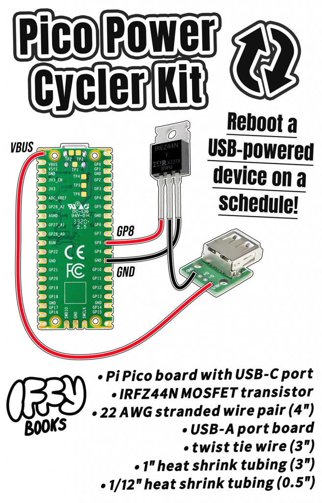
Here are the parts you’ll need to complete this project:
- Pi Pico board with USB-C port
- IRFZ44N MOSFET transistor
- 22 AWG stranded wire pair (4″)
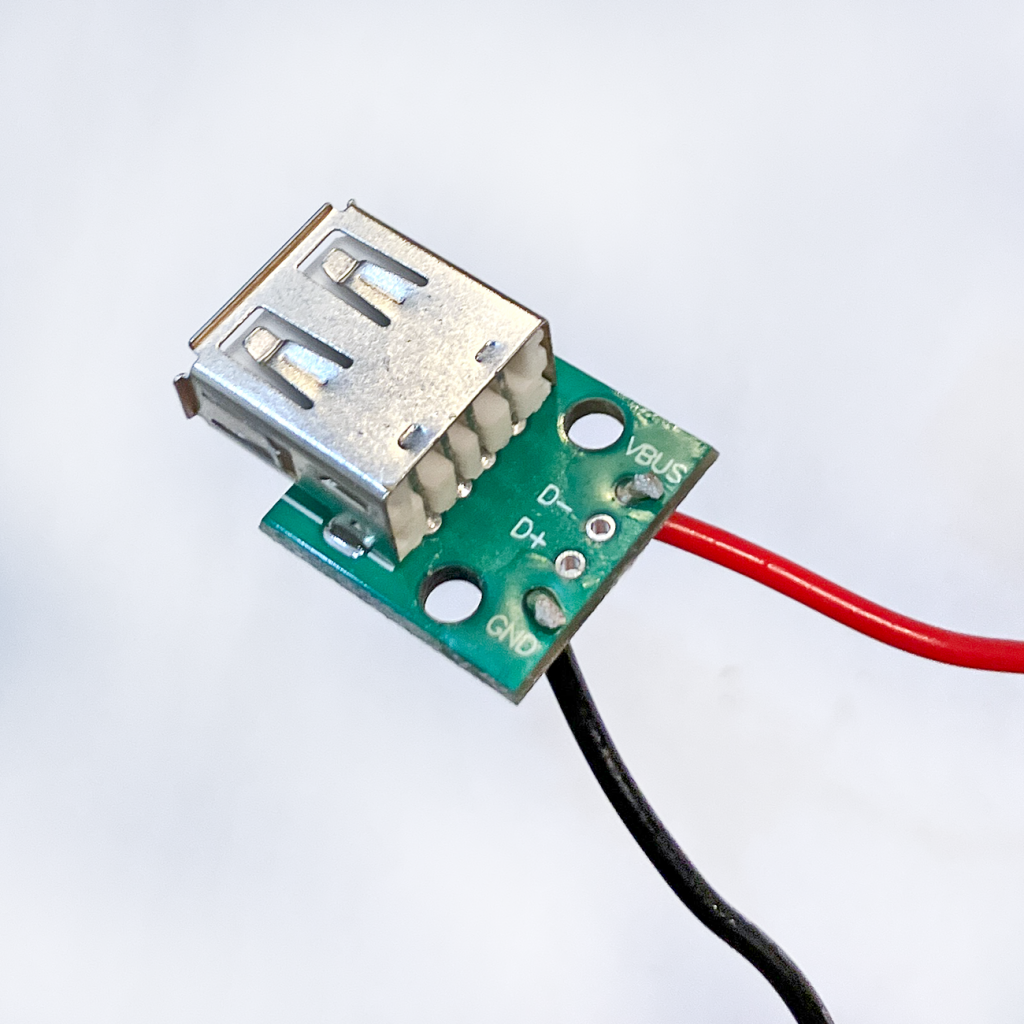
- USB-A port board
- twist tie wire (3″)
- 1″ heat shrink tubing (3″)
- 1/12″ heat shrink tubing (0.5″)
Install Thonny IDE
❏ Visit Thonny.org and download the Thonny IDE for your operating system (macOS, Windows, or Linux).
Install CircuitPython firmware
❏ Download the CircuitPython firmware file from the following page:
https://circuitpython.org/board/raspberry_pi_pico
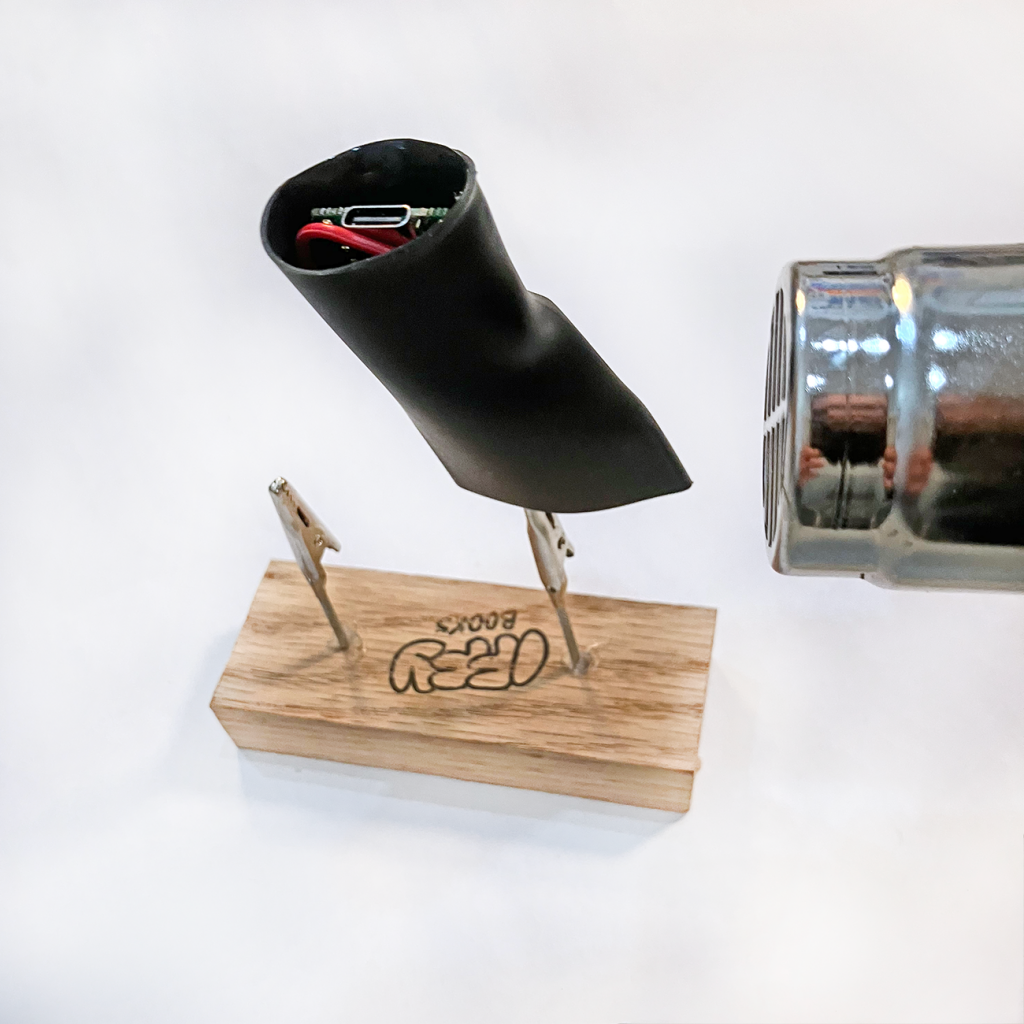
❏ Connect a USB-C cable (with data) to your Pi Pico board.
❏ Press the white BOOTSEL button on your Pi Pico while plugging the other end of the USB-C cable into your computer. Once it’s plugged in you can release the button.
❏ You’ll see a USB drive called RPI-RP2 appear on your computer. Drag the CircuitPython firmware file (ending with .uf2) to the RPI-RP2 drive.
That’s it! The RPI-RP2 drive will disappear and a new one called CIRCUITPY will appear in its place.
Save CircuitPython code to your Pi Pico
❏ Open Thonny and save this example code to your Pi Pico with the filename code.py:
https://github.com/iffybooks/pico-power-cycler/blob/main/code.py
❏ Click the green Run button to run your code.
❏ Every time you update your code, you’ll save it and then click Run. If you get an error when you try to save your code, click the Stop button and try again.
Solder black wire to MOSFET
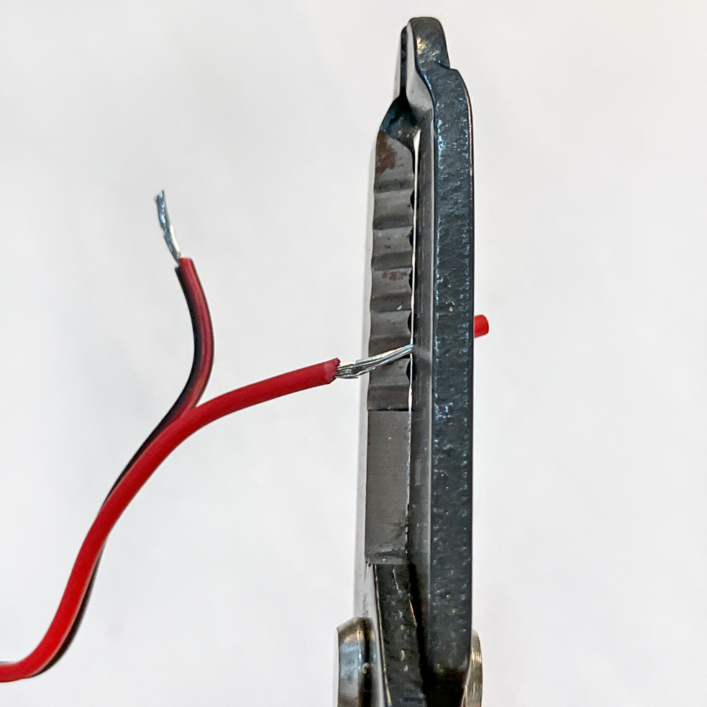
❏ Split your stranded wire pair at each end and use wire strippers to remove ~1/3″ (1 cm) of insulation from the end of each wire.
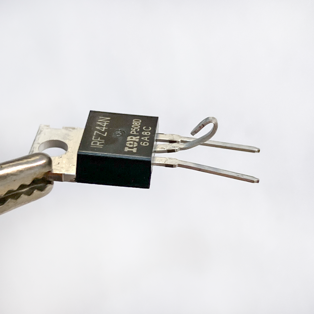
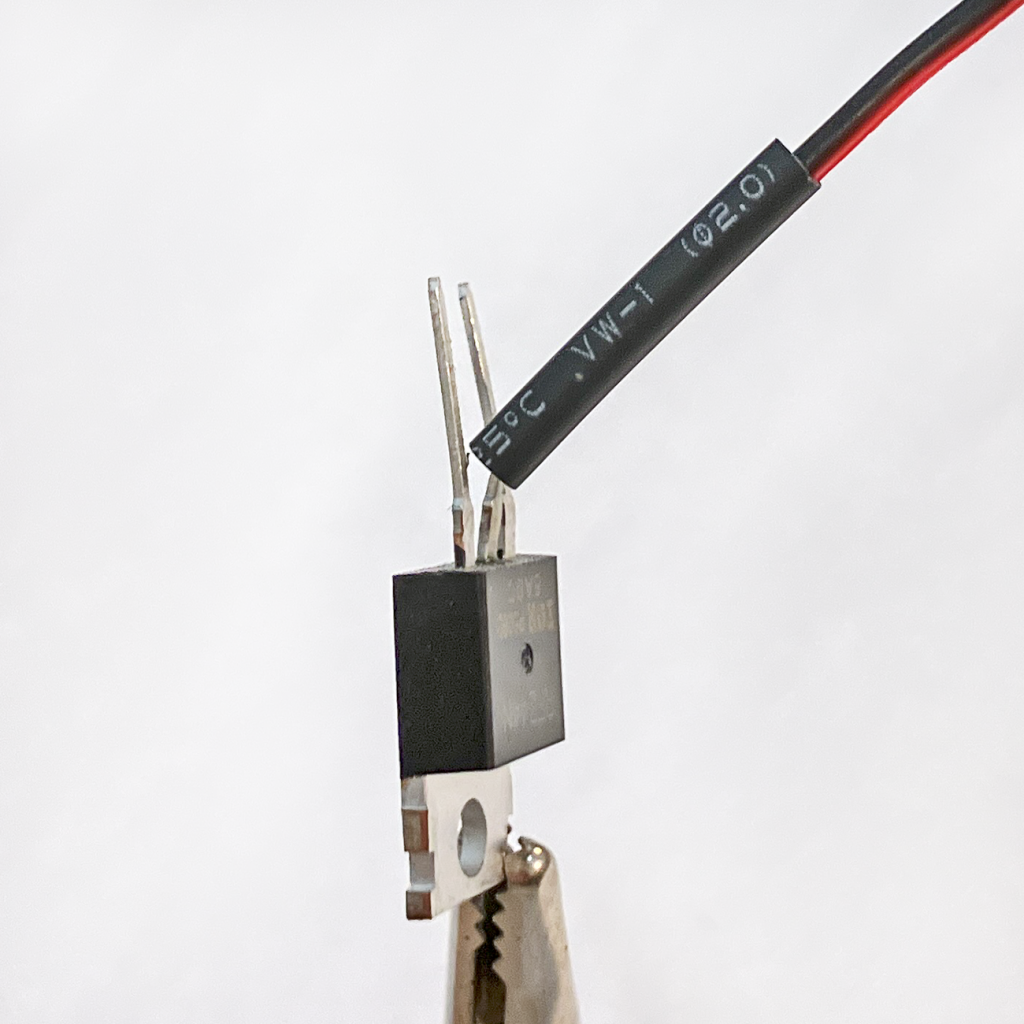
❏ Using pliers or the end of your wire stripper tool, bend the MOSFET’s middle lead to make a hook shape.
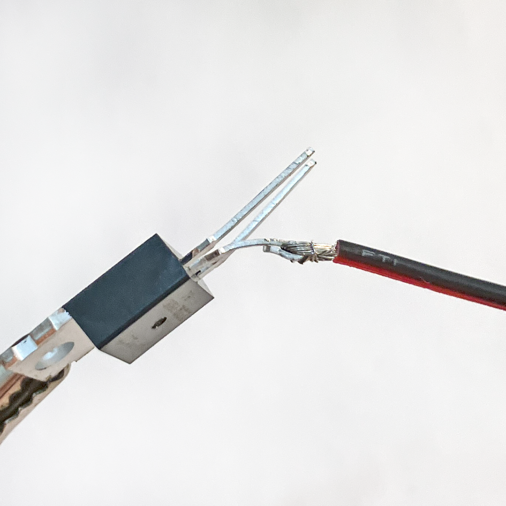
❏ Put the exposed end of your black wire into the hook and fold it over. Then use pliers or the end of your wire stripper tool to crimp down the MOSFET lead.
❏ If you have a helping hands tool, clip your MOSFET in place with the leads pointing up.
❏ Apply flux paste to the wire and lead (optional but recommended). Set your soldering iron to 310°C, get a big blob of solder on the tip, and hold it to the connection point for 3–5 seconds to get everything hot enough.
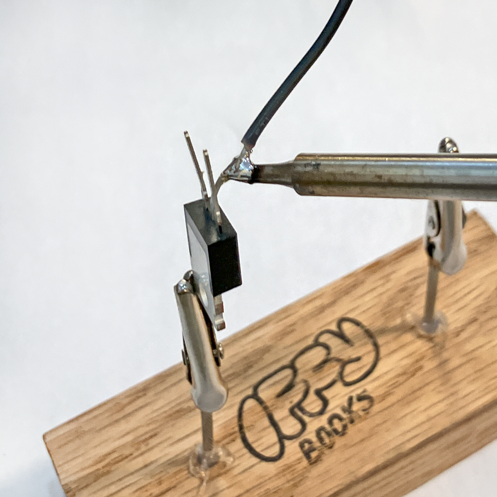
❏ Slide the 1/12″ heat shrink tubing over the area you just soldered, then use a heat gun or hairdryer to shrink it in place.
Solder MOSFET to Pi Pico
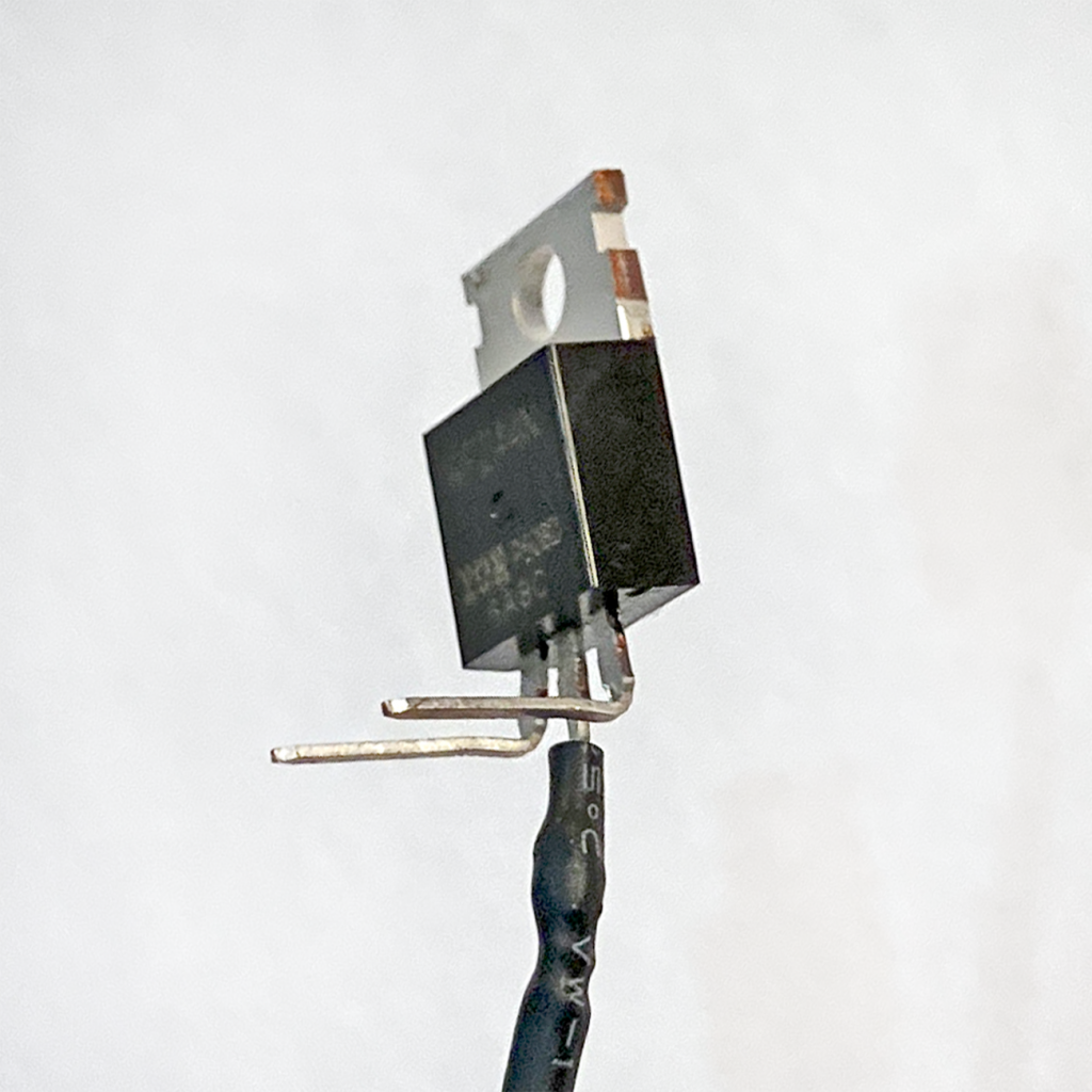
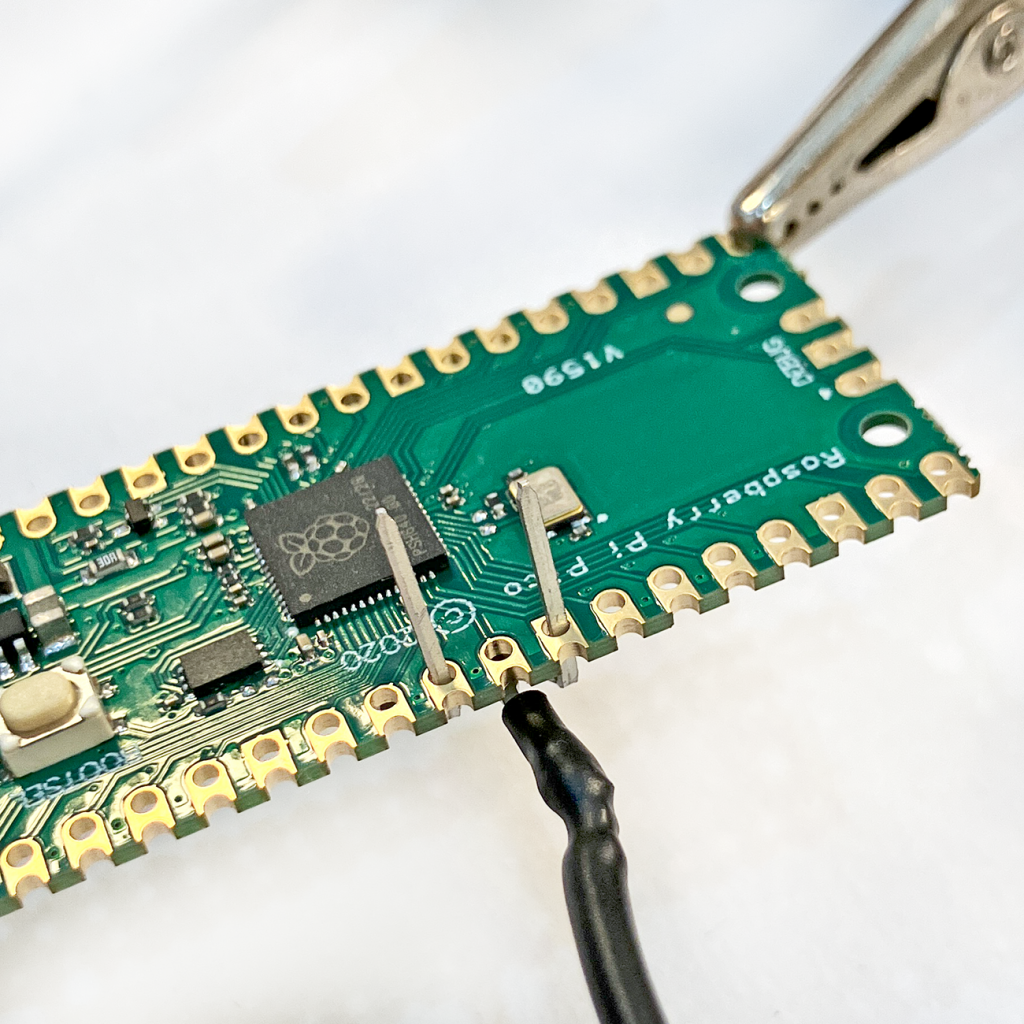
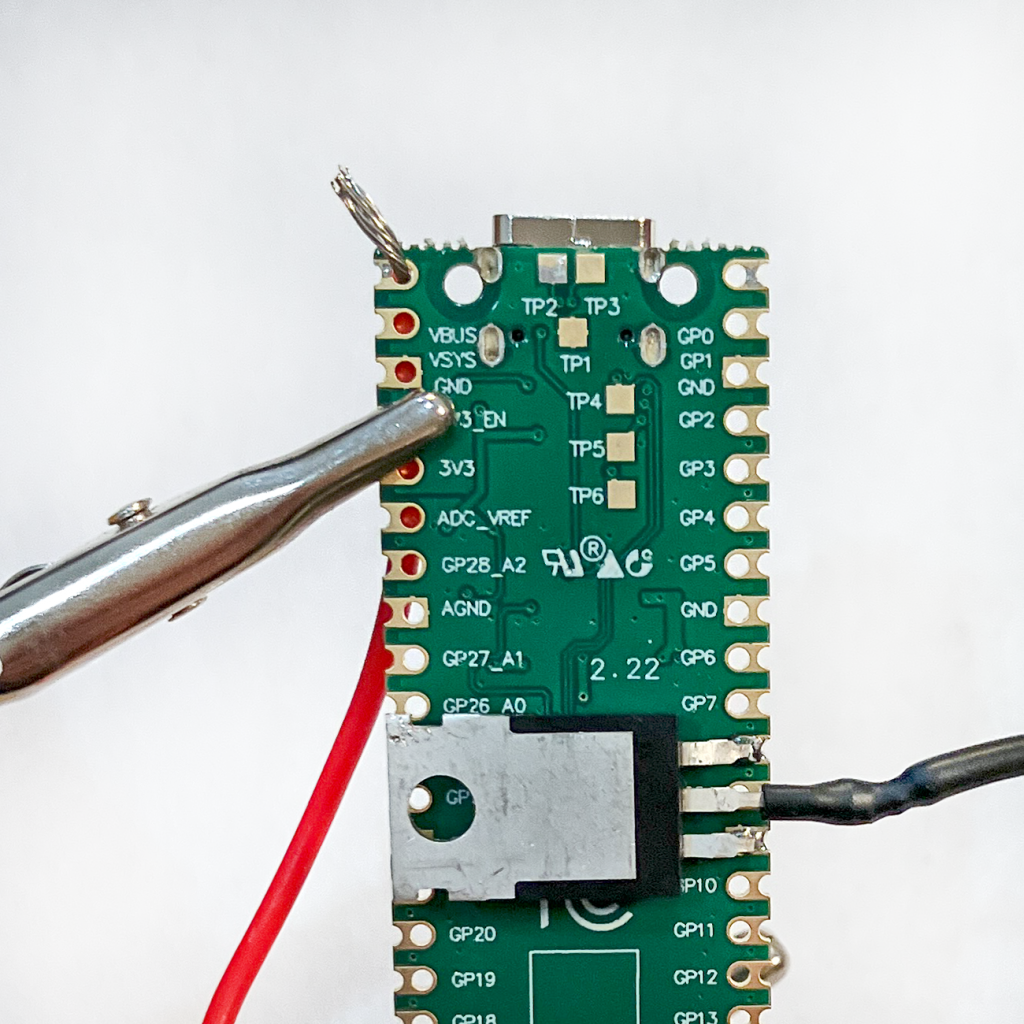
❏ Bend the left and right leads of your MOSFET forward at a right angle. (Check the photo below to make sure it matches.)
❏ Line up the left and right leads of your MOSGET with GP8 and GND on the back of your Pi Pico board. (Check the photos below to make sure they match.)
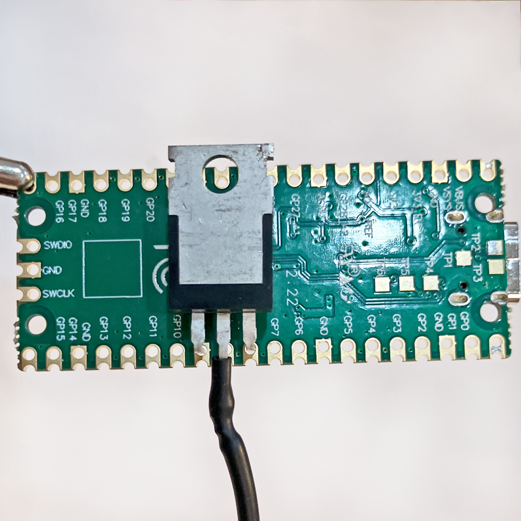
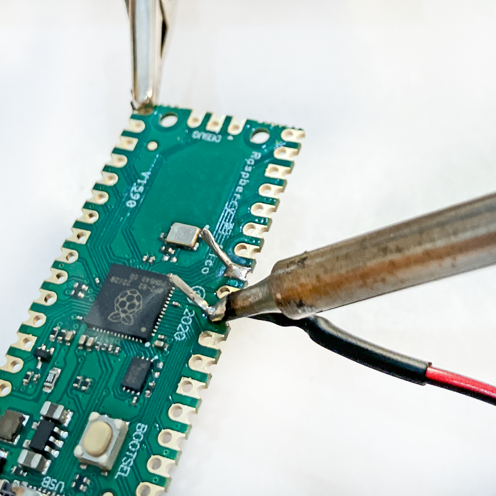
❏ Apply flux paste to the solder joints. Then get your iron and solder them!
❏ Use wire cutters to trim the excess MOSFET leads.
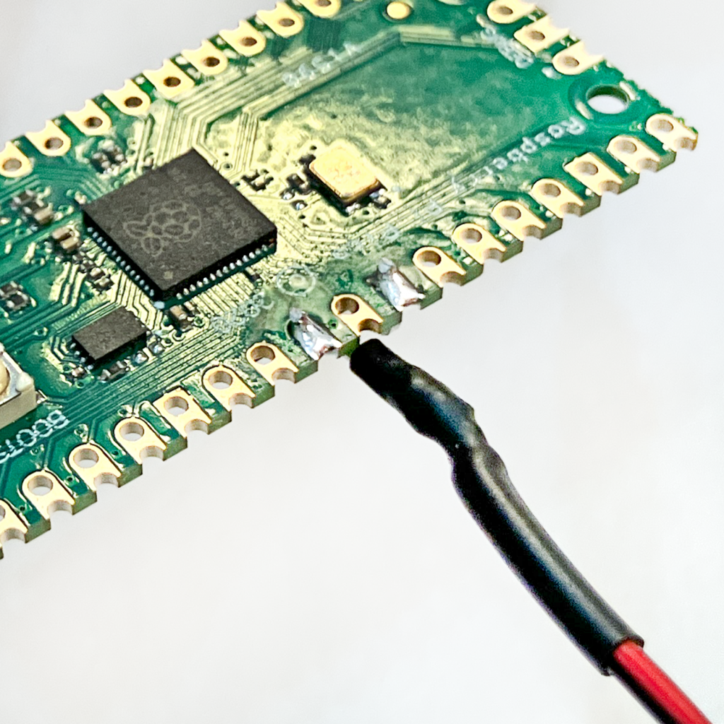
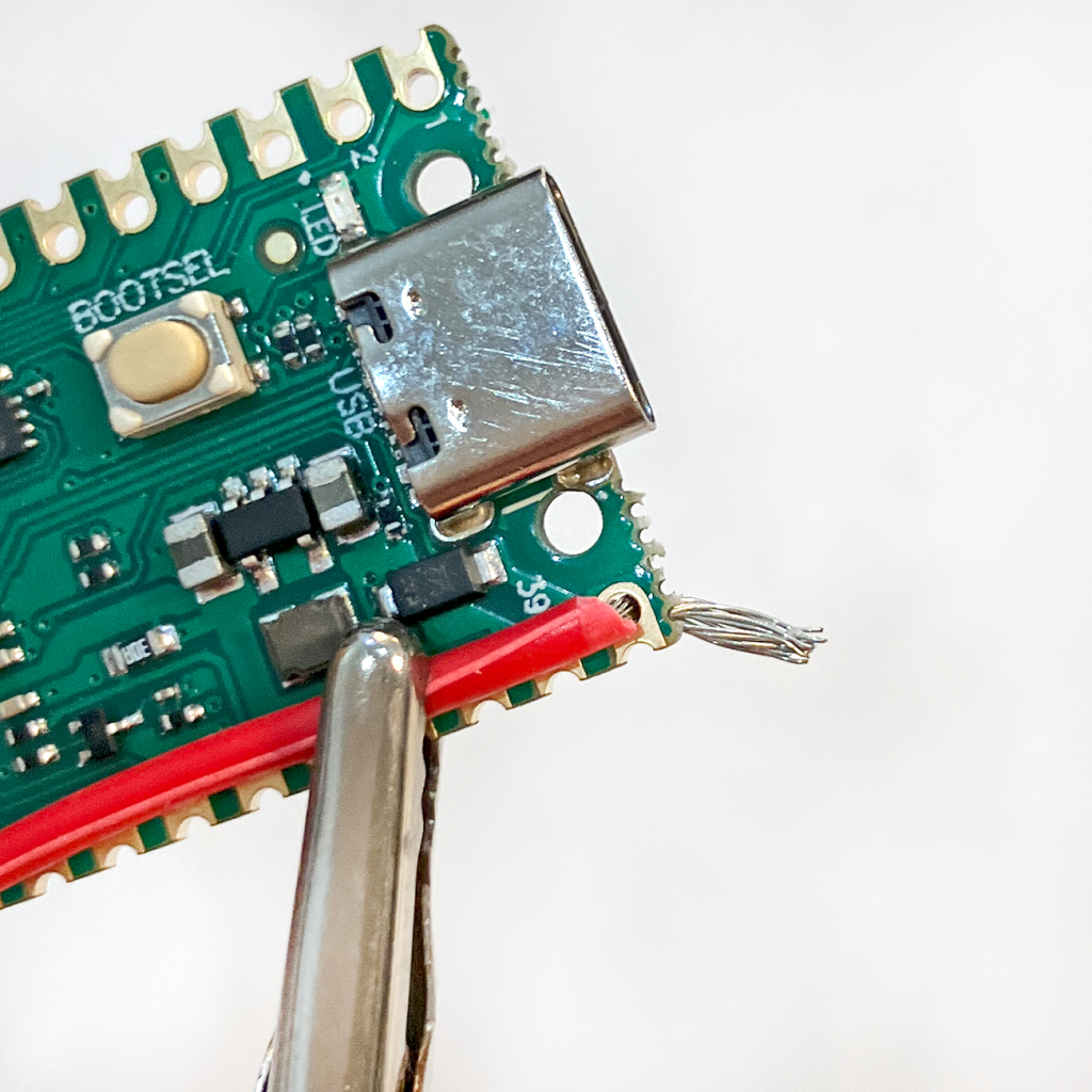
❏ Twist one end of your red wire together and pass it through the VBUS pin on your Pi Pico (either direction works). Apply flux paste, solder the joint, and trim off the excess wire.
❏ Twist the free end of your black wire together and pass it through the GND pin hole on your USB-A port board. Do the same with your red wire, passing it through the VBUS pin hole. Apply flux paste, solder the joints, and trim off the excess wire.
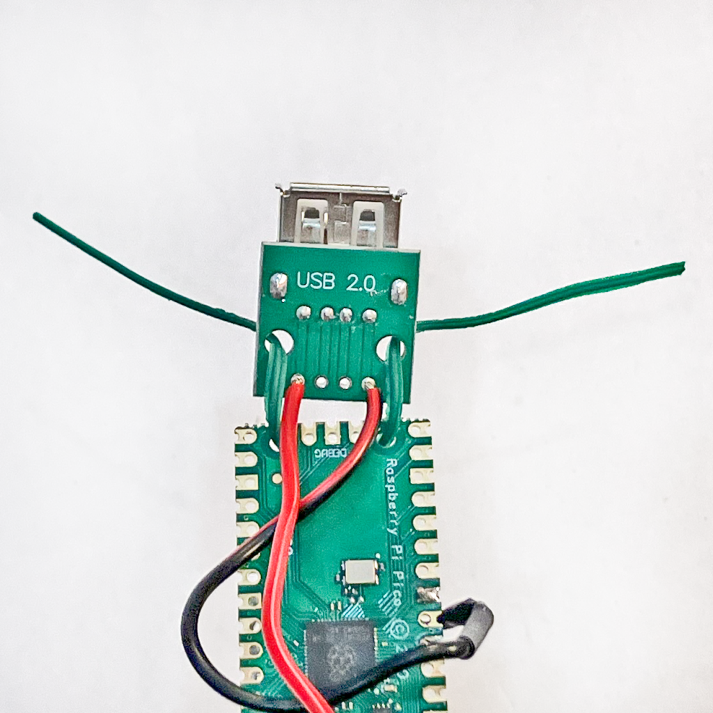
❏ Pass twist tie wire through the screw holes at the bottom of the Pi Pico board, then through the holes on the USB-A port board. Twist the wire together to hold everything in place.
❏ Now you’ll test it out! Connect a USB-powered device to the USB-A port, then connect a powered USB-C cable to the Pi Pico board. The example code will turn the connected device on for 3 seconds, off for 3 seconds, then repeat.
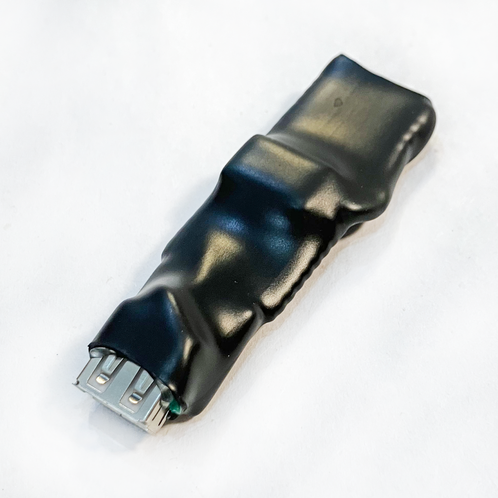
❏ If your test worked, it’s time to enclose your Pico power cycler device in 1″ heat shrink tubing. Clip your helping hands tool to the USB-A port so you can keep your hands away from the device for the next step.
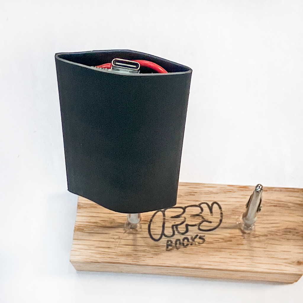
❏ Use a heat gun or hair dryer to shrink the tubing around your device. Heat shrink tubing stays hot for a long time! Give it a solid 5 minutes to cool down.
Your finished Pico Power cycler should look something like the photo below. Nice work!
To reprogram your device, connect it to your computer and open the file code.py with Thonny or any plaintext editor. You can edit the time.sleep() lines to adjust how long, in seconds, your USB-powered device will be turned on and off. The example code below leaves it on for 1 hour, turns it off for 3 seconds, then repeats.
# Pico Power Cycler Kit
# 2025 Iffy Books (wtfpl)
# https://iffybooks.net/pico-power-cycler

import board
import digitalio
import time

# Initialize MOSFET pin
mosfet_pin = digitalio.DigitalInOut(board.GP8)
mosfet_pin.direction = digitalio.Direction.OUTPUT

# Infinite loop
while True:
	# Turn power on
	mosfet_pin.value = True
	time.sleep(60*60)
	# Turn power off
	mosfet_pin.value = False
	time.sleep(3)