In this workshop you’ll use a Pi Pico microcontroller to send low-res (320×240) digital video to an HDMI display. Despite its limitations, the cool thing about this device is that it’s inexpensive enough that you can plug it in somewhere (perhaps a wall of TVs at an electronics store) and leave it behind for prank/art/propaganda purposes. The term “throwie” usually refers to a battery-powered device such as an LED light or radio transmitter with magnets on the back, tossed onto a high metal surface where it can’t easily be reached.
Your Pi Pico will generate video in the DVI-D format rather than the newer HDMI standard. But because HDMI is backwards compatible with DVI-D, your device should work with any HDMI monitor or TV.
Here’s what’s in your kit:
- Pi Pico board w/ microUSB port
- Pico DVI video sock
- insulated wire (4″)
- heat shrink tubing (3″)
Here’s what else you’ll need:
- HDMI cable
- microUSB cable with data connection
- computer (macOS/Linux/Windows)
- soldering iron
- lead-free solder
- flux paste
- header pins (optional)
- wire stripping tool (optional)
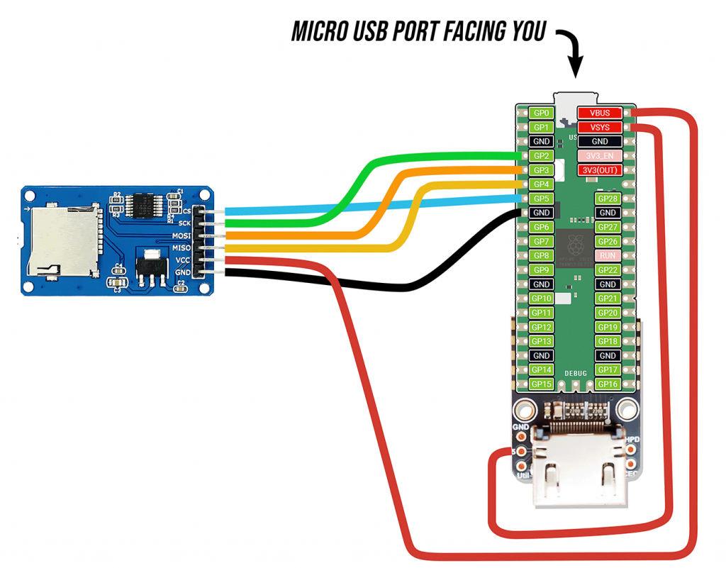
Solder DVI sock to Pi Pico board
❏ Place the DVI sock under the bottom end (opposite the microUSB port) and carefully align the pads along the edges. You may find it helpful to use header pins (sometimes included with Pi Pico boards) to keep them in place. Use the single-core wire or a spare PCB to support the other end of the Pi Pico board. Here are the connections you’ll be making:
- GP12 to D0+
- GP13 to D0-
- GP14 to CK+
- GP15 to CK-
- GP16 to D2+
- GP17 to D2-
- GP18 to D1+
- GP19 to D1-
- GND to GND
Note: If you don’t have a DVI sock board, you should be able to replicate this setup by sacrificing an HDMI cable. Cut the cable, strip the wires, solder a 220 ohm resistor to each relevant wire, and solder them to your Pi Pico. We’ll update this guide if someone gets around to trying it.
❏ Apply a small amount of flux paste to each solder joint using a toothpick or scrap of wire.
❏ Set your soldering iron to 300°C and solder each joint.
Connect 5V power
❏ Find the 4″ (10 cm) length of wire in your kit. Use wire stripping tool to remove ~1/3″ (1 cm) of insulation from each end.
❏ Connect the “5” pin on the DVI sock to the “VSYS” pin on the Pi Pico.
❏ Apply flux paste and solder both ends of the wire in place.
Install CircuitPython firmware
❏ Download the CircuitPython firmware file from the following page:
https://circuitpython.org/board/raspberry_pi_pico
❏ Connect a microUSB cable (with data) to your Pi Pico board.
❏ Press the white BOOTSEL button on your Pi Pico while plugging the other end of the USB-C cable into your computer. Once it’s plugged in you can release the button.
❏ You’ll see a USB drive called RPI-RP2 appear on your computer. Drag the CircuitPython firmware file (ending with .uf2) to the RPI-RP2 drive.
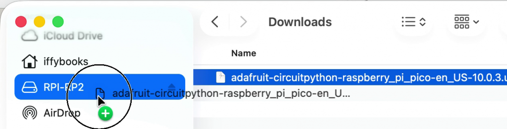
That’s it! The RPI-RP2 drive will disappear and a new one called CIRCUITPY will appear in its place.
Install Thonny IDE
❏ Visit Thonny.org and download the Thonny IDE for your operating system (macOS, Windows, or Linux).
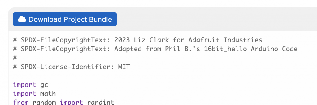
Download Adafruit example code
❏ Visit the following URL and click the blue “Download Project Bundle” button. Unzip the file when it’s complete.
https://learn.adafruit.com/adafruit-dvi-sock-for-pico/circuitpython
Save CircuitPython code to your Pi Pico
❏ Make sure your HDMI throwie device is plugged into your computer.
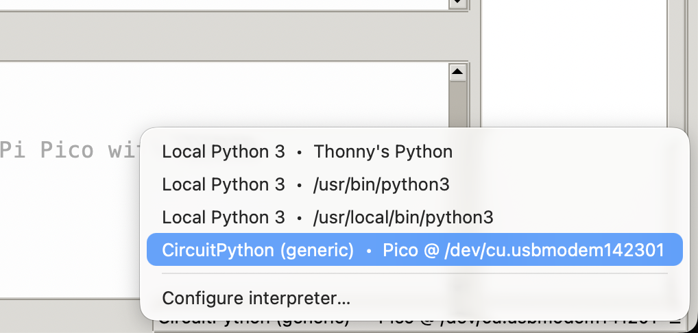
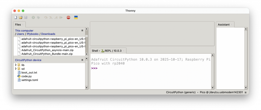
❏ Open Thonny. In the far bottom right corner of the window, click the text that says “CircuitPython (generic)” or “Local Python” and you’ll see a dropdown menu. Select the CircuitPython option that has a USB serial port listed next to it.
❏ In the menu bar, select View > Files and a column will appear on the left side showing the files on your local system (top) and your Pi Pico (bottom).
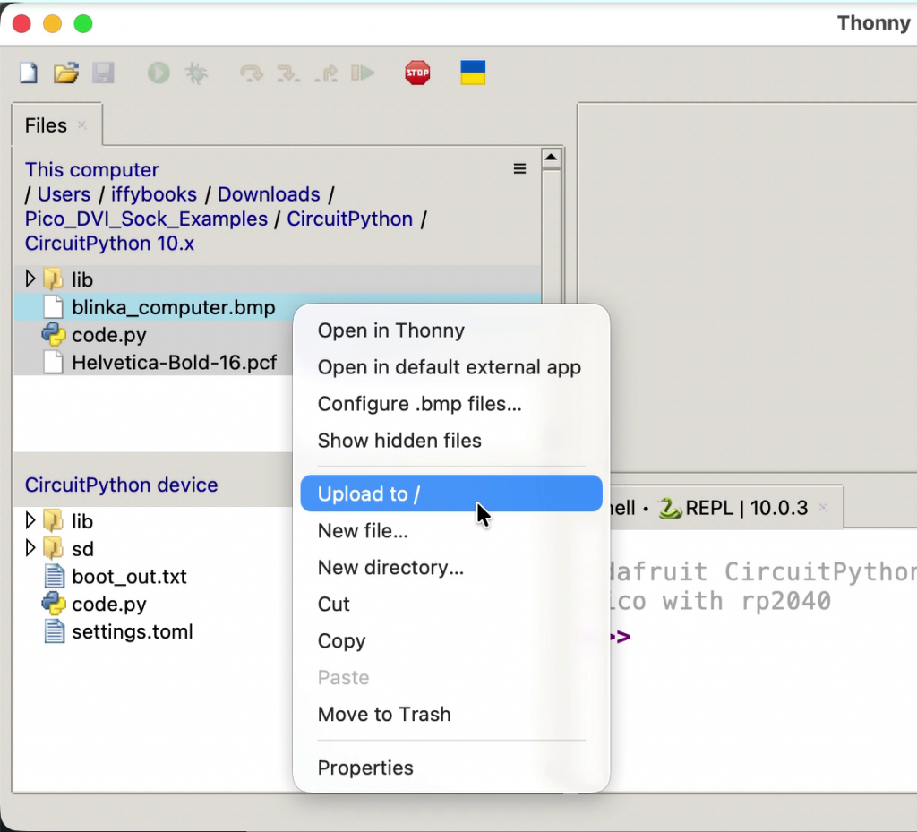
❏ In the top window, navigate to your Downloads folder and find the Pico_DVI_Sock_Examples directory you just downloaded. Then go to the CircuitPython directory, followed by CircuitPython 10.x.
❏ Select all the files in this directory, then right click and select Upload to / from the dropdown menu.
❏ An alert window will ask if you want to overwrite the existing files on your device. Click Yes.
❏ In the lower window in the files column, double click code.py to edit it.
❏ Click the green Run button at the top of the window to run your code.
❏ Every time you update your code, you’ll save it and then click Run. If you get an error when you try to save your code, click the Stop button and try again.
Here’s more info on the example code we’re using:
https://learn.adafruit.com/adafruit-dvi-sock-for-pico
Connect HDMI throwie to a display
❏ Connect your HDMI throwie to a TV, monitor, or projector using an HDMI cable.
You should see video!
Bouncing DVD menu
❏ To generate video with bouncing text like a DVD player meny, copy and paste the code below into code.py. You’ll replace all the code in the file.
https://iffybooks.net/wp-content/uploads/2026/01/HDMI_Throwie_DVD_Menu_Code.py.txt
Screed loop text display
https://iffybooks.net/wp-content/uploads/2026/01/Screed_Loop_Throwie.zip
Bitmap slideshow
https://iffybooks.net/wp-content/uploads/2026/01/Info_Kiosk_Throwie.zip
Here’s an ImageMagick command to convert an image called image.png to a .bmp bitmap image file.
magick image.jpg -define bmp:ignore-filesize -size 320x240 image.bmpAnd here’s one to convert every file in the current directory!
find . -name “*.jpg” -exec magick {} -define bmp:ignore-filesize -size 320×240 {}.bmp \;
Bitmap slideshow with SD card reader