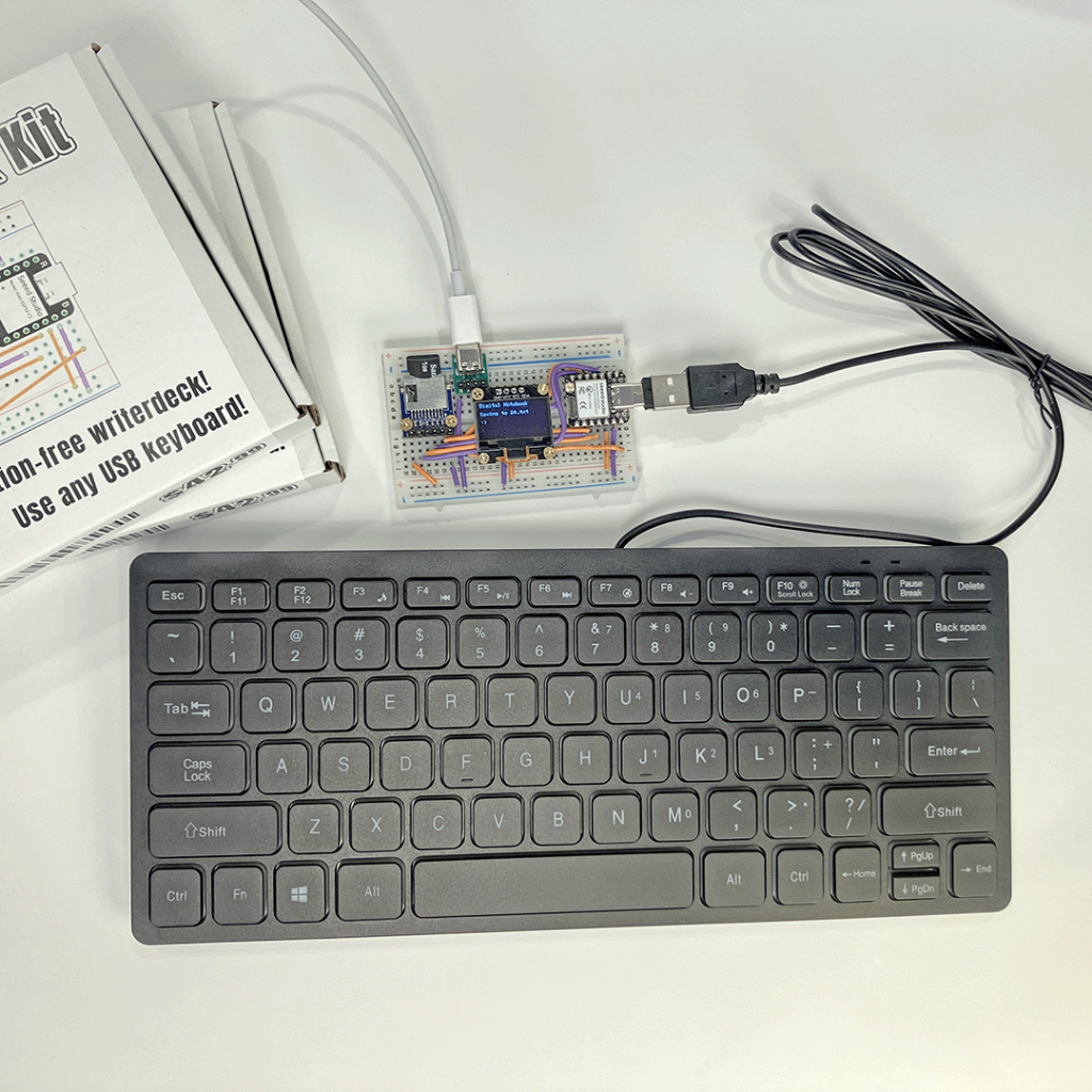
In this workshop you’ll build a digital notebook, a pocket-sized device for taking notes with a USB keyboard. We’re using affordable, widely available components: a Seeed XIAO ESP32-S3 microcontroller, a 1-inch OLED display, and a microSD card reader, arranged on a solderless breadboard. The ESP32-S3 connects to the display via the I2C (Inter-Integrated Circuit) protocol, and to the microSD card reader using the SPI (Serial Peripheral Interface) protocol.
Folks who have a basic familiarity with programming/electronics will get the most out of this project, but no specific knowledge is required. You’ll be cutting and stripping some wires, which requires a degree of manual dexterity.
Here’s what you’ll need to complete this project:
- Seeed XIAO ESP32-S3 MCU board
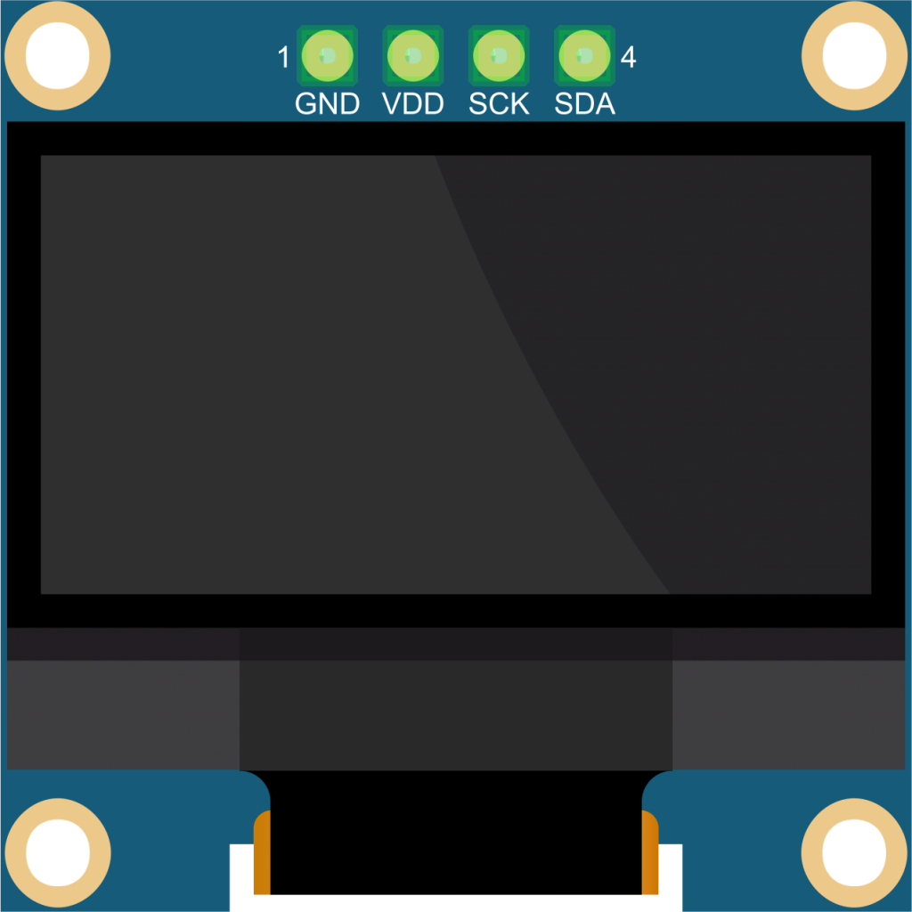
- 0.96″ OLED display (SSD1306)
- microSD card reader w/ 6-pin SPI interface
- USB-C port w/ 4 header pins
- 400 tie point solderless breadboard
- 5 Volt 1 Amp power brick with USB-A port
- USB-A to USB-C cable
- 2 USB-C to USB-A adapters
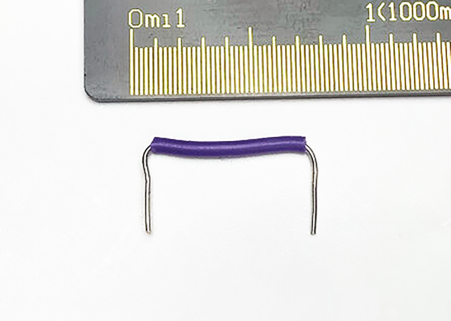
- Single-core 22AWG jumper wire (30″)
- Wire cutter/stripper tool
- 6 self-tapping M2 screws
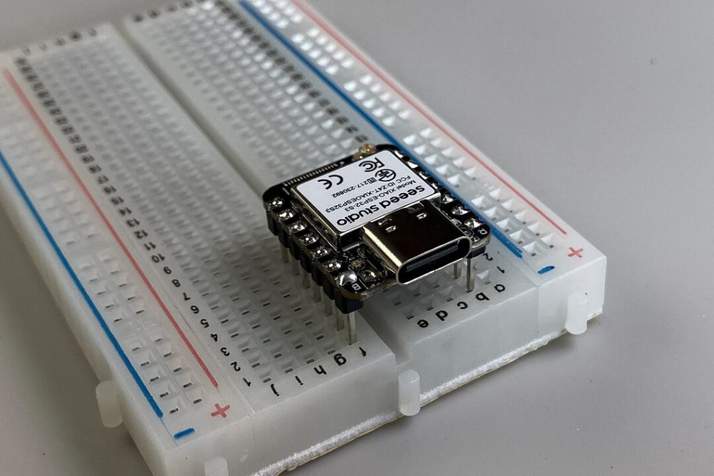
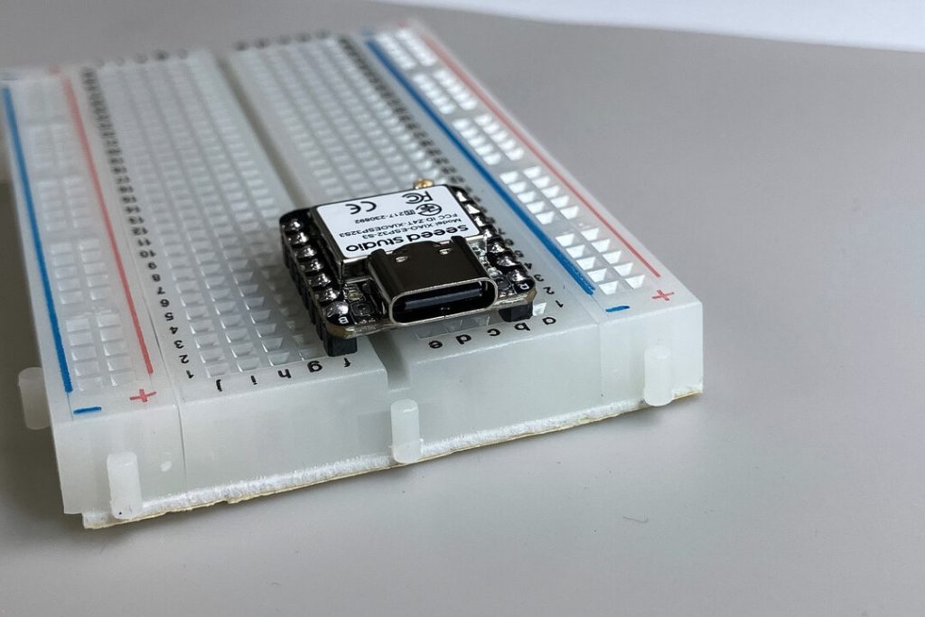
We’ll be referring to the ESP32-S3 development board by the more general term MCU, short for microcontroller unit.
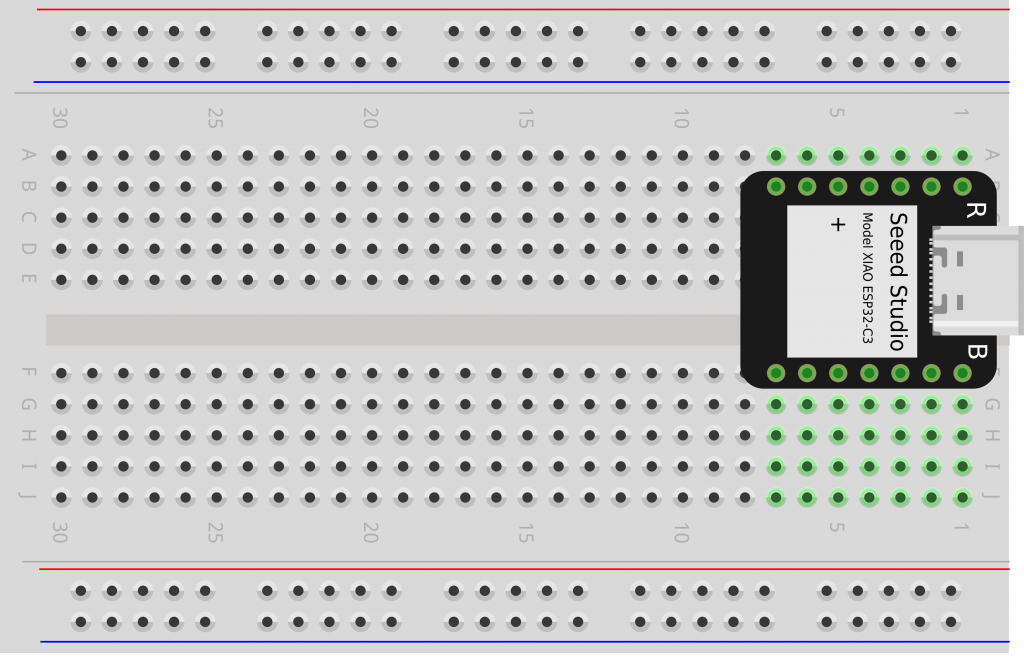
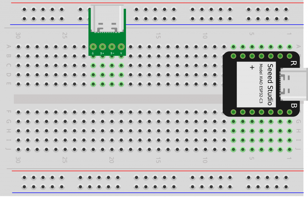
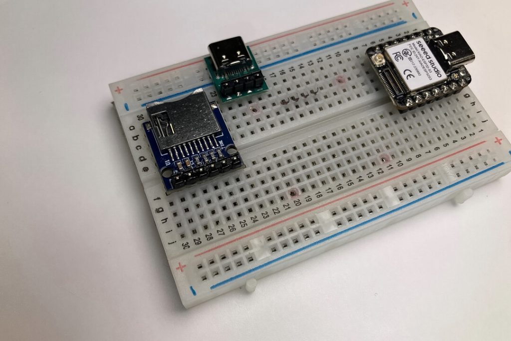
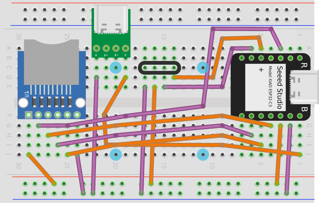
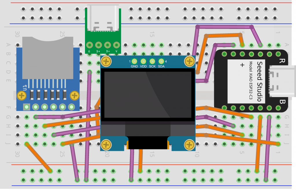
❏ Line up the MCU‘s header pins with column B and column F on your breadboard, with the USB-C side starting at row 1. Press it down to secure in place.
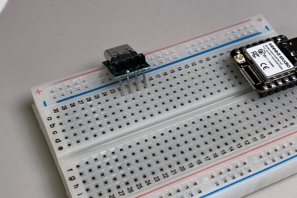
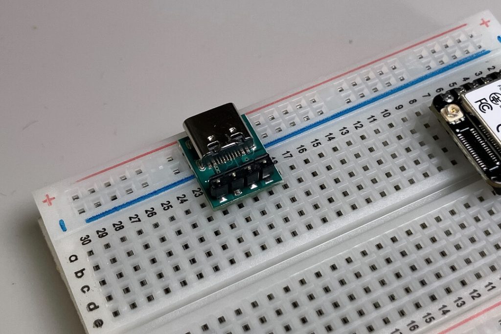
❏ Line up the USB-C port‘s header pins with column A, rows 19–22 and press down.
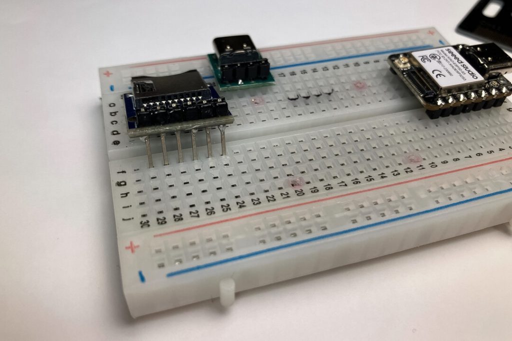
❏ Line up the microSD card reader‘s header pins with column F, rows 24–29 and press down. Note: We’re leaving one row unused (row 30) to the left of the microSD card reader.
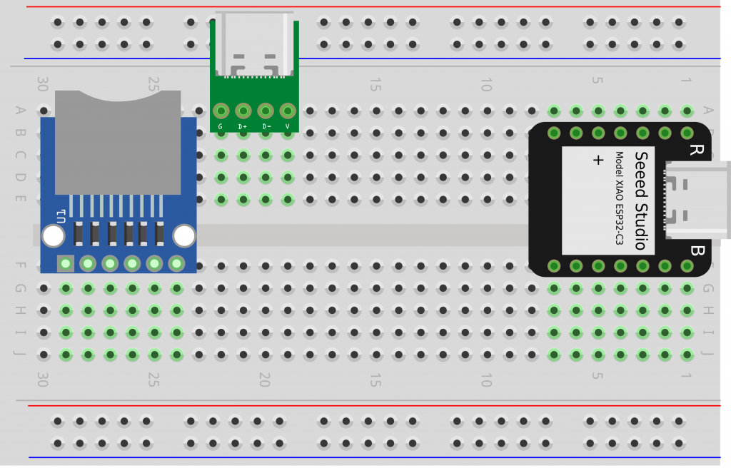
❏ Optional: Use a marker to draw a rectangle around the four tie points where you’ll attach your OLED screen later in the project: column C, rows 14–17.
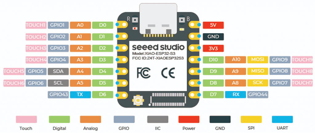
Here’s a pinout diagram for the Seed XIAO ESP32-C3 MCU.
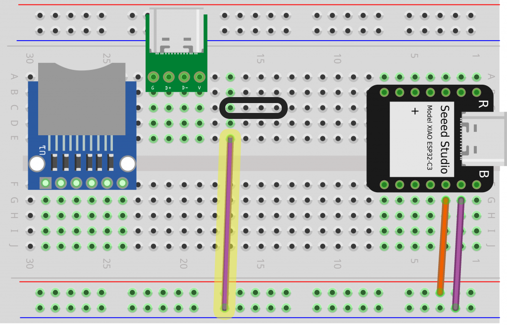
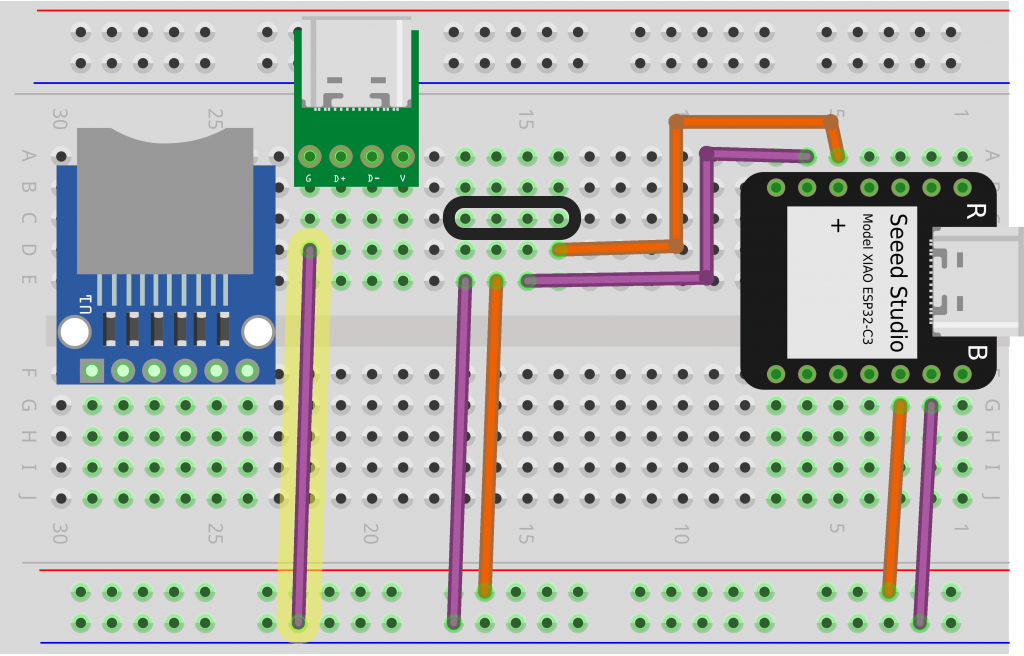
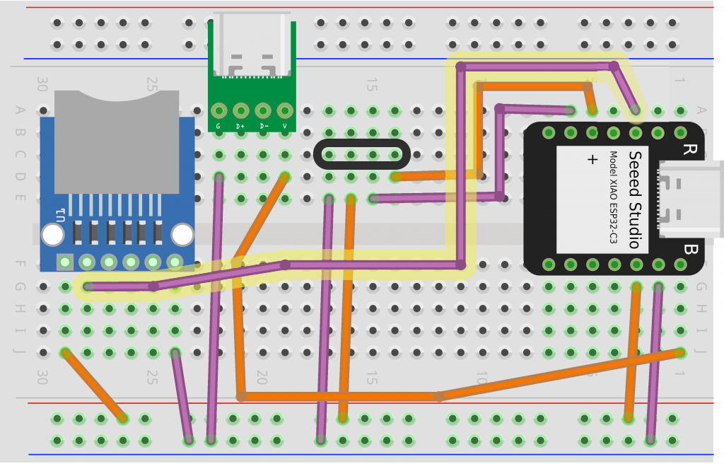
❏ You’ll start by connecting the ground pin on the MCU (column G, row 2) to the ground rail, the column on the bottom edge with a blue stripe next to it. Cut a length of wire roughly 1″ longer than the distance between the two tie points, then strip the plastic insulation from each end and make the connection.
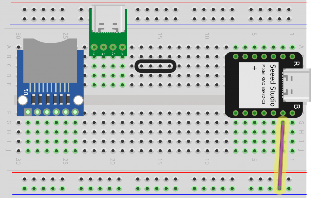
❏ Connect the 3.3V pin to the 3.3V rail (above the ground rail, next to the red line). This is how you’ll provide power to the OLED screen and microSD card reader.
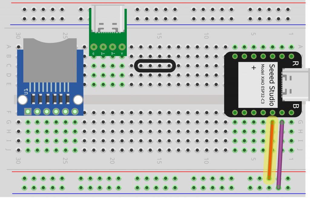
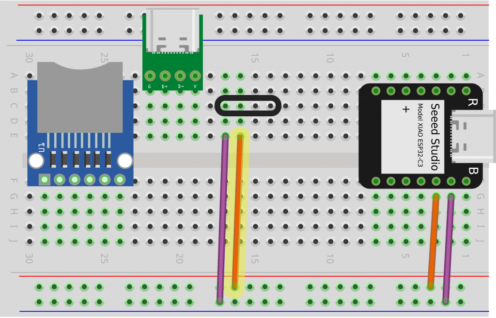
Next you’ll you’ll add connections for the SSD1306 OLED screen, which you’ll attach once all the wires are in place.
❏ Connect column E, row 17 to the ground rail, next to the blue line.
❏ One row over, connect column E, row 16, to the voltage rail (red line side).
❏ Next connect your OLED screen’s SCL pin (column E, row 15) to D5/GPIO6 on the MCU (column A, row 6).
SCL is short for serial clock line, where the MCU plays a steady unchanging pulse to keep a piece of hardware in sync.
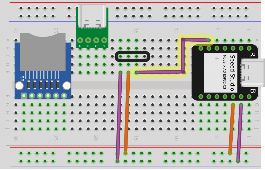
❏ Connect your OLED screen’s SDA pin (column E, row 14) to D4/GPIO5 on the MCU (column A, row 5).
SDA is short for serial data line, where the MCU sends data to a piece of hardware.
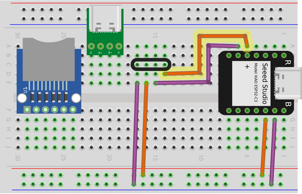
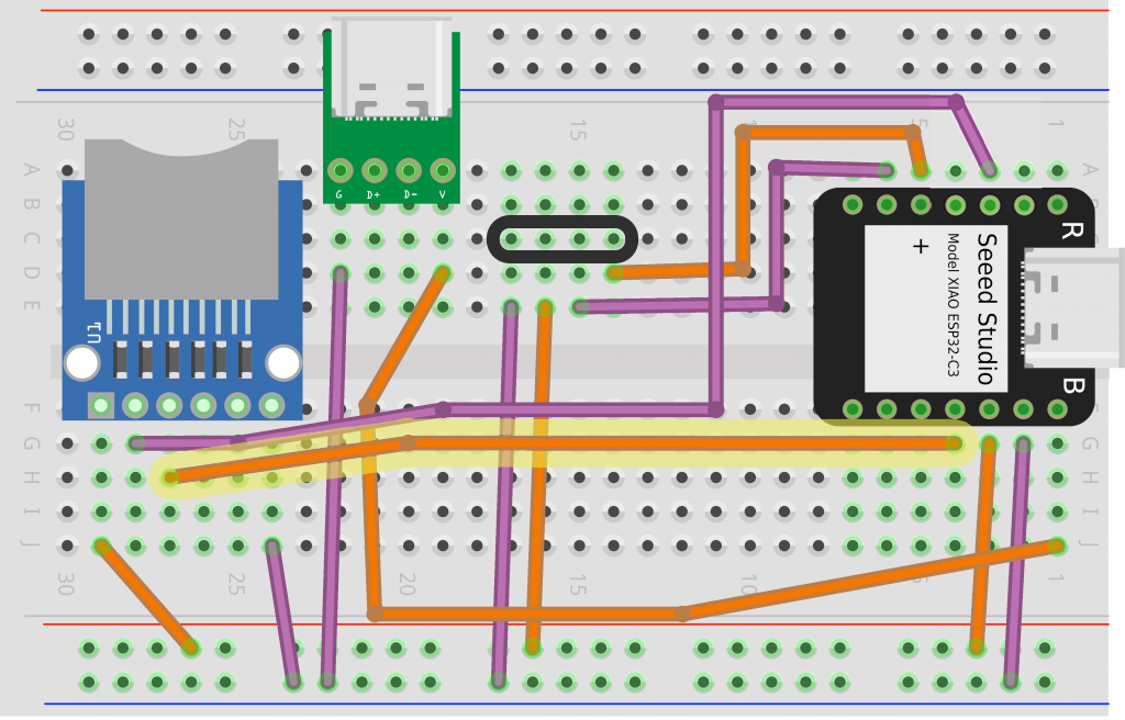
❏ Now we’ll move on to the USB-C port, which will provide 5V power to the MCU. Connect the ground pin (G) (column D, row 22) to the ground rail.
❏ The USB-C port’s voltage (V) pin connects to the 5V pin on the MCU, so you’ll need a wire about twice as long as the last step. Starting at column D, row 19, curve your wire to the left slightly before connecting to column J, row 1 in the bottom right corner.
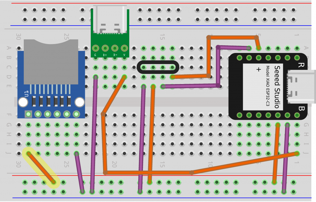
❏ We’ll move on to the microSD card reader. Connect the ground (GND) pin (column J, row 24) to the ground rail.
❏ Next, connect the microSD card reader’s voltage (VCC) pin (column J, row 29) to the voltage rail.
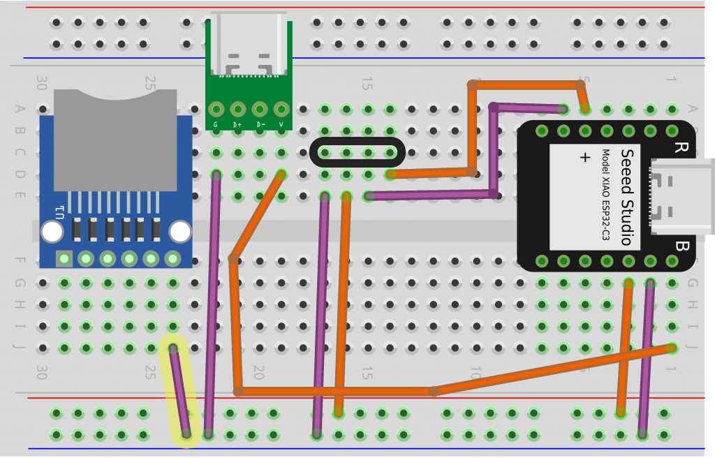
❏ Connect the microSD card reader’s CS pin (column G, row 28) to D2/GPIO3 on your MCU (column A, row 3).
❏ The microSD card reader’s MOSI pin (column H, row 27) connects to D10/GPIO9 on your MCU (column G, row 4).
You can remember MOSI as main out, secondary in. It’s where the MCU (main device) will send data out to the microSD card reader (secondary device).
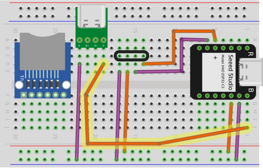
❏ Connect the CLK pin (column I, row 26) on the microSD card interface to D8/GPIO7 on your MCU (column H, row 6). CLK is short for clock.
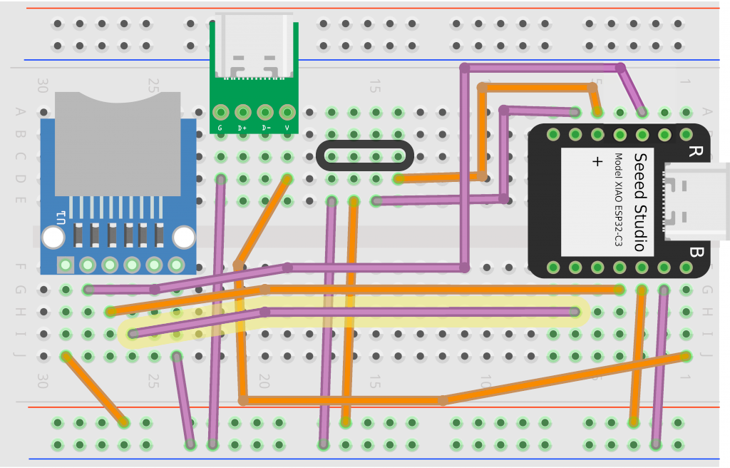
❏ Connect the microSD card reader’s MISO pin (column J, row 25) to D9/GPIO8 on the MCU (column I, row 5).
You can remember MISO as main in, secondary out. It’s where the microSD card reader (secondary device) will send data out to the MCU (main device).
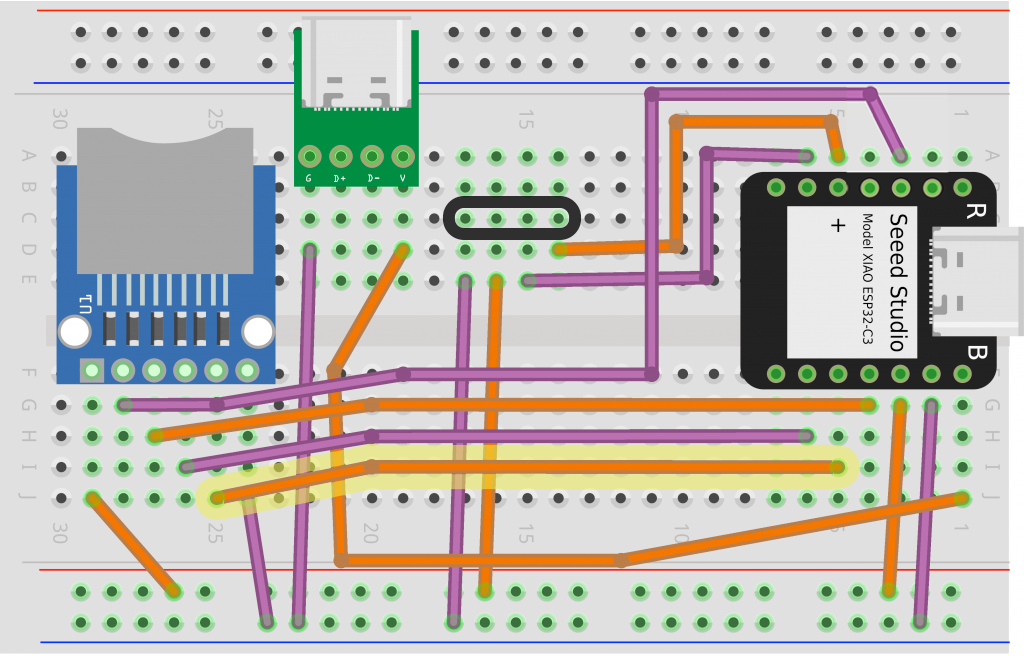
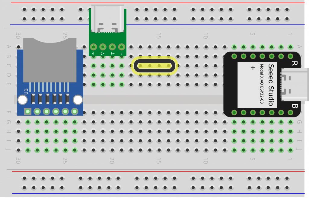
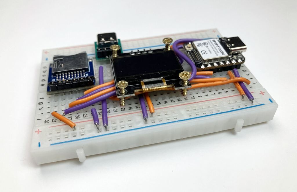
❏ Line up the OLED screen and note where the four screws at the corners will be going in (indicated in blue below). Then rearrange your wires if needed so they aren’t in the way.
❏ Line up the OLED screen’s header pins with the four tie points you marked earlier. Press it into place.

Later we’ll screw the OLED screen into place. For now, let’s install the software and make sure everything works!
Download Arduino IDE and install ESP32 packages
❏ Go to Arduino.cc and click Download to download the Arduino IDE.
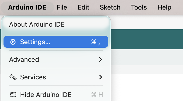
❏ Launch the Arduino IDE application, then open Settings.
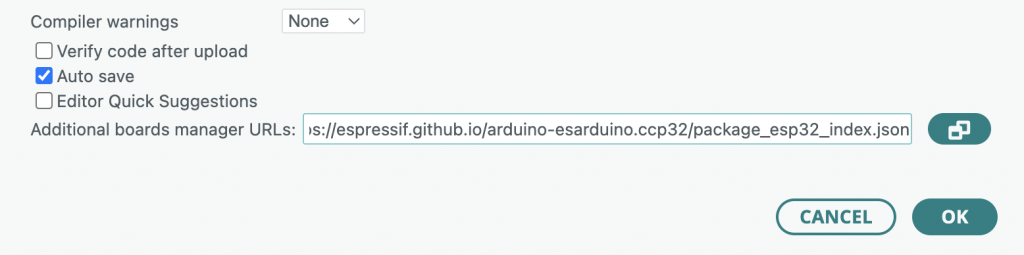
❏ Copy and paste the following URL into the Additional board manager URLs text box. Then click OK to save.
https://raw.githubusercontent.com/espressif/arduino-esp32/gh-pages/package_esp32_index.json
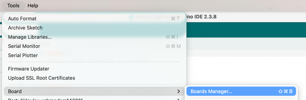
❏ In the menu bar, go to Tools > Board > Boards Manager.
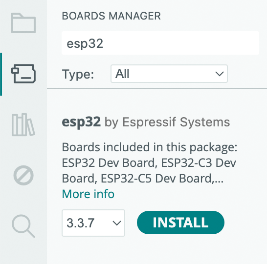
❏ Search for “esp32” in the boards manager column. Find the package called esp32 by Espressif Systems and click INSTALL.
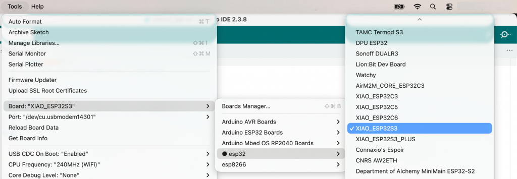
❏ In the menu bar, go to Tools > Board > esp32 > XIAO_ESP32S3 to select the type of development board you’ll be using.
More details on installing ESP32 Arduino packages:
https://docs.espressif.com/projects/arduino-esp32/en/latest/installing.html
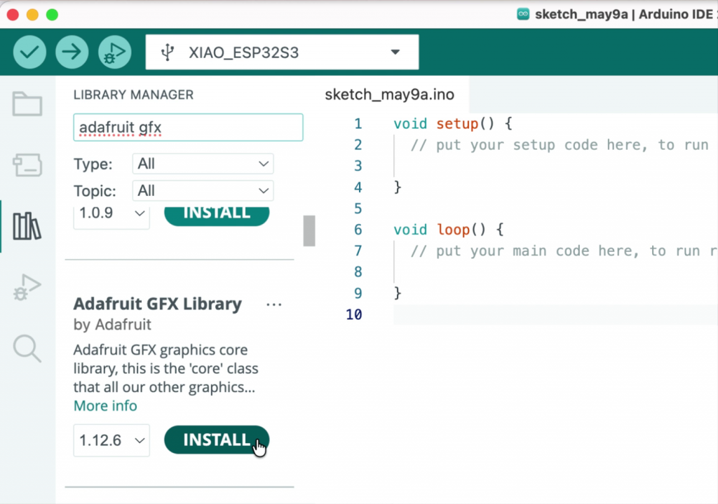
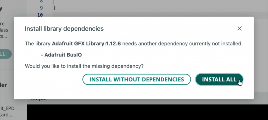
Install Adafruit GFX library
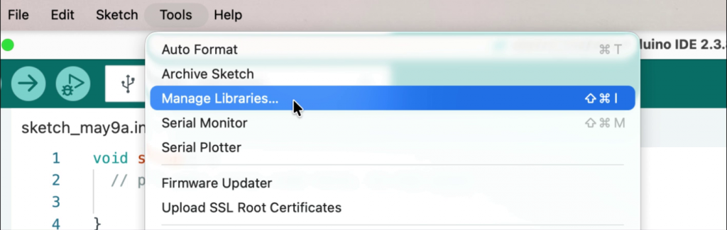
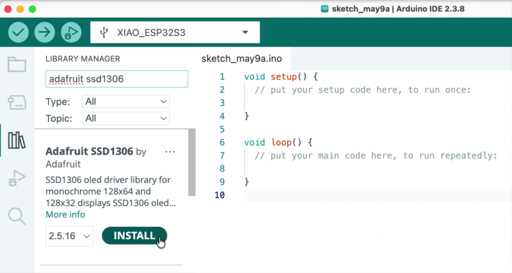
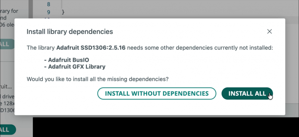
Install Adafruit SSD1306 library
Download Digital Notebook code
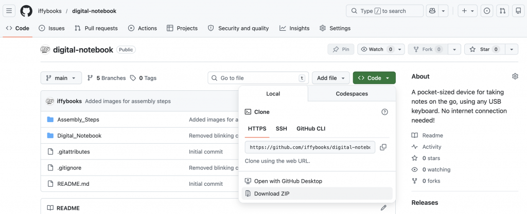
❏ To download the firmware code for your digital notebook, go to the following URL. Then click Code > Download ZIP to download the code bundle.
https://github.com/iffybooks/digital-notebook
Open the .ino file with the Arduino IDE
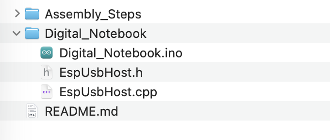
❏ Find the file digital-notebook-main.zip in your Downloads folder and double click to unzip it.
❏ In the directory digital-notebook-main you’ll find a subdirectory called Digital_Notebook with all the Arduino files you’ll need. Double click Digital_Notebook.ino to open it with the Arduino IDE.
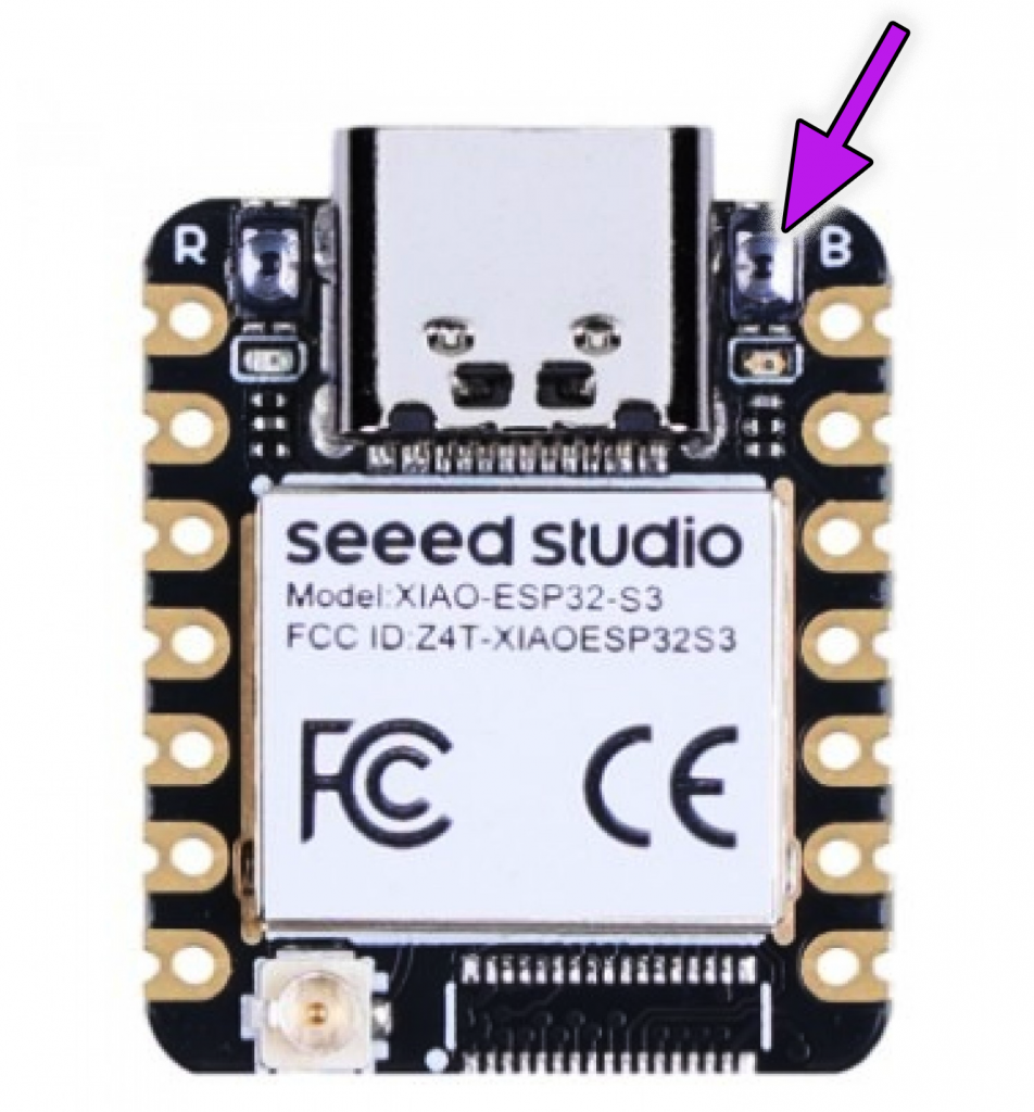
Connect MCU to your computer while pressing B button
❏ On your ESP32S3 MCU, look for the letter B beside the USB-C port. If you squint you’ll see a teeny-tiny button next to it, known as the boot select button. To enter boot select mode, press the button down while connecting the device to your computer with a USB-C cable. Once the USB-C cable is connected you can release the button.
Note: If you have trouble pressing the button with your fingernail, try using a pen cap or one of the USB-C to USB-A adapters included in your kit.
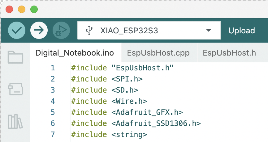
❏ In the Arduino IDE, go to Tools > Port and select your device’s USB port from the menu. If you don’t see your device, go back to the previous step.
[img]
Flash software to the MCU
❏ Click the arrow icon at the top left corner of the Arduino window to compile and upload the firmware code to your device.
Insert microSD card
❏ Insert a microSD card into the microSD card reader. A new card should work fine. If you’re reformatting an old one, be sure to use FAT32 format.
Connect 5V power
❏ Connect the USB-A to USB-C cable to your 5V 1 Amp power brick. Then connect the USB-C end of the cable to the USB-C port above your device’s screen. You should see text on the screen!
Connect a USB keyboard
❏ Using a USB-C to USB-A adapter, connect a USB keyboard to the USB-C port on the MCU on the right side of your device).
❏ Type a few letters and you should see them onscreen! Every four seconds, your digital notebook device checks whether you’ve updated the document. If so, your work will be saved to the microSD card.
Screw hardware into place
❏ Unplug the USB-C power cable.
❏ Optional: To keep the USB-C power port from falling out, you may want to move its header pins to column B before completing the steps below. That way the top edge of the OLED screen will hold it in place.
❏ Pass M2 screws through the four corners of the OLED screen and line them up with the tie points below.

❏ Screw in the four screws with a Phillips head screwdriver. To avoid cracking the OLED screen, tighten each screw a little bit before moving on to the next one, rotating around several times.
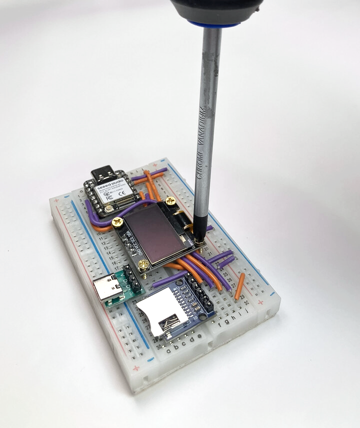
❏ Finally, pass two M2 screws through the holes in the microSD card reader and screw them into place with a Phillips head screwdriver. In this case you’ll be screwing into solid plastic rather than tie points, so you’ll need to apply some pressure.
Great job! Good luck with writing!